Category:
3D
Date:

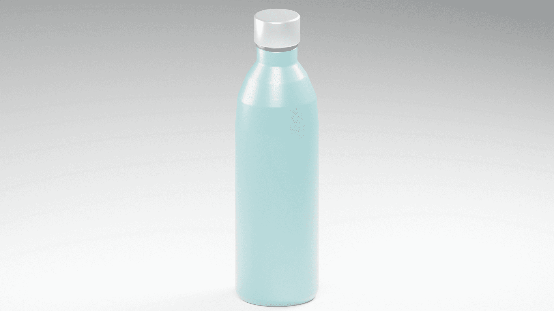
For my second exercise in MMD60804 3D Modeling, the task was to replicate a water bottle using the blueprint provided by our teacher. The main body had to begin as a cylinder and be shaped in Edit Mode, using loop cuts, extrusion or inset, and bevels.
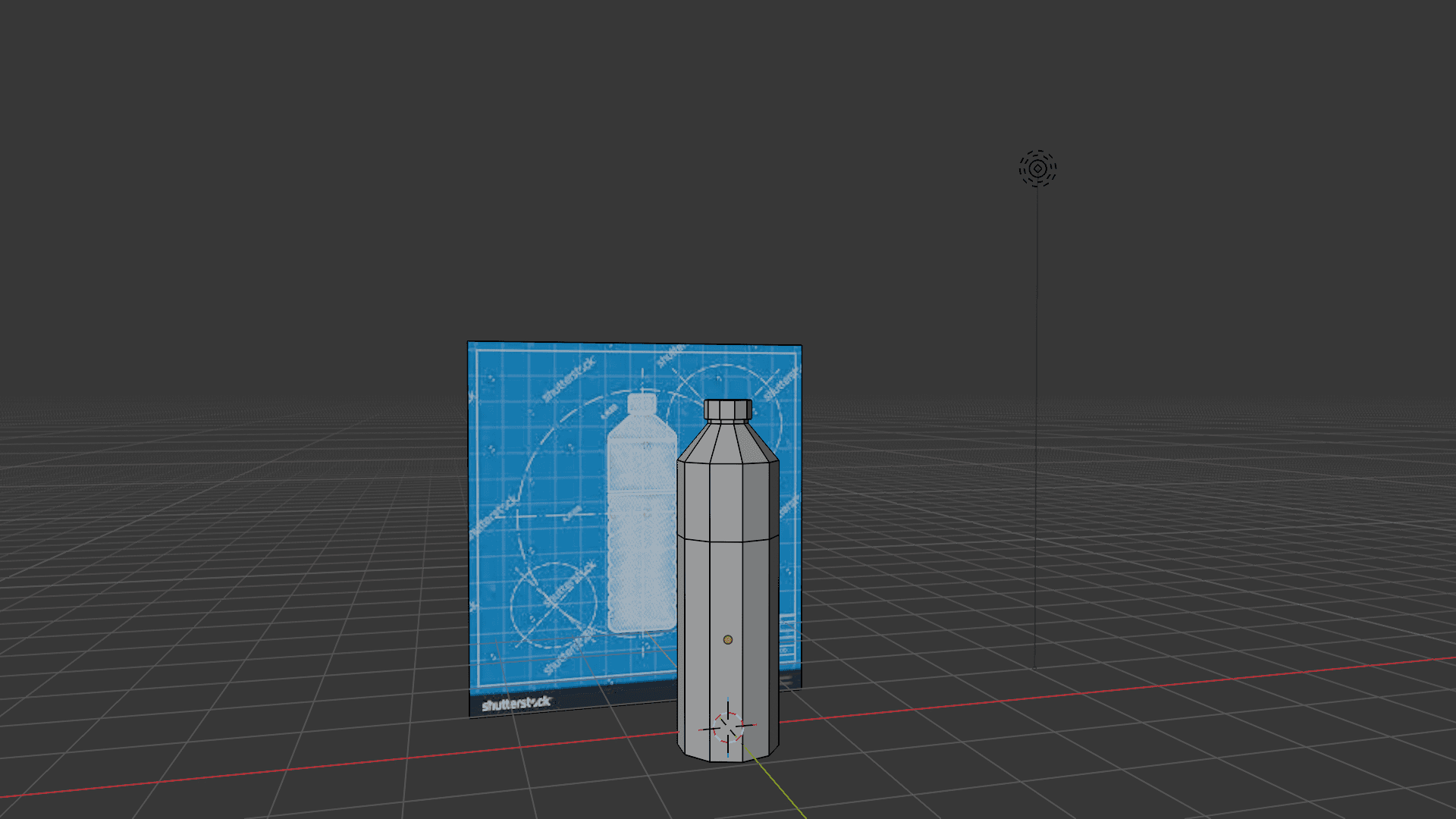
The reference showed a tall bottle with a narrow neck, a small cap, sloping shoulders, and repeated ridges around the lower body. My aim was to reproduce these features while learning how mesh-editing tools control an object’s shape.
1. Studying the Blueprint
The first step was to study the reference and identify the features that made the bottle recognisable.
Reference feature | Modelling approach |
|---|---|
Tall cylindrical body | Scale the starting cylinder to establish the proportions |
Narrow neck | Scale the upper sections inward |
Sloping shoulder | Shape the transition between the body and neck |
Repeated lower ridges | Add and shape horizontal loop cuts |
Rounded transitions | Bevel edges to simulate curves |
Small cap | Define the short top section above the neck |
The blueprint gave me a clear target for the silhouette and the placement of details. It helped me focus on matching an existing design rather than inventing the shape as I worked.
2. Choosing and Proportioning the Cylinder
Q. The cylinder vertex count you chose, and why ?
Ans. Based on my recollection, I chose a cylinder with 12 vertices. This offered a manageable amount of geometry for selecting and scaling loops while establishing a rounded bottle shape.
I adjusted the cylinder’s proportions to resemble the tall, narrow body in the blueprint. Establishing the main silhouette first made it easier to judge the size of the shoulder, neck, and cap.
3. Using Loop Cuts to Replicate the Ridges
Q. How many loop cuts you used ?
Ans. I used 8 loop cuts, based on my recollection, to develop the repeated ridges shown around the lower body of the reference.
The loops divided this area into horizontal sections. Adjusting these sections created the changes in profile that made the ridges visible.
This taught me that loop cuts are useful for reproducing specific details from a reference. Their placement and spacing affect how closely the finished model matches the original design.
The saved mesh contains additional edges from later detailing, so the original count of eight loop-cut operations cannot be independently confirmed.


4. Shaping the Shoulder and Neck
The blueprint showed the bottle narrowing above the main body. I shaped the upper sections to create a sloping shoulder leading into a smaller neck.
This transition was important to the overall silhouette. The body, shoulder, and neck needed to work together so that the bottle looked like the reference rather than a straight cylinder with a cap.
I learned to compare the widths of neighbouring sections instead of judging each part separately.
5. Using Bevels to Simulate Curves
I used bevels to simulate the curved transitions in the reference. Bevelled edges introduced smaller faces between adjoining surfaces, softening abrupt changes in the profile.
This was particularly useful for making the bottle’s details appear less sharp. The aim was to suggest the rounded shape of a manufactured plastic bottle.
This stage helped me understand that bevel width affects the character of a model. A small bevel can soften an edge, while a larger bevel changes the silhouette more noticeably.

6. Applying Materials
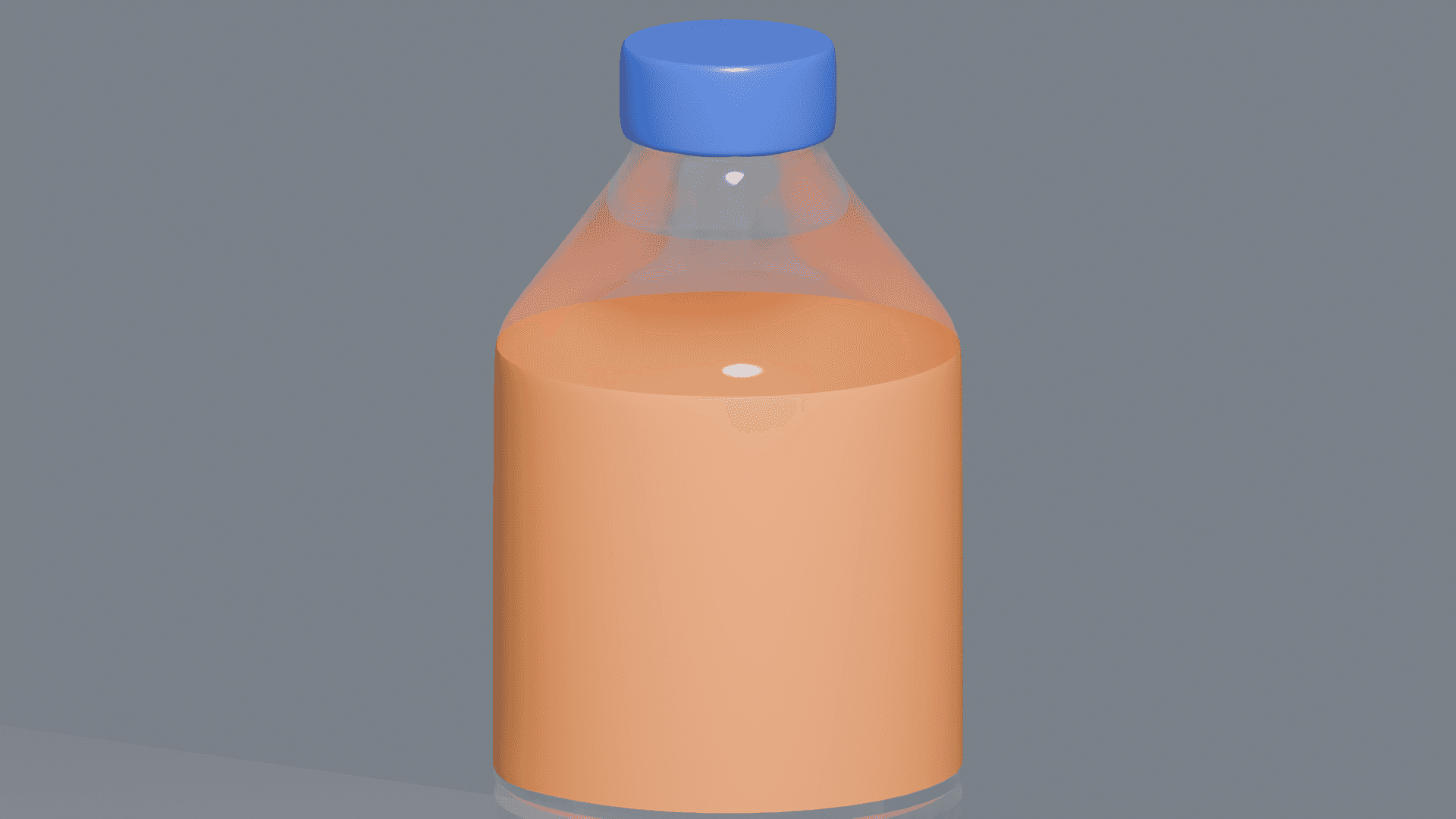
After developing the shape, I used contrasting materials to distinguish the bottle’s sections.
Section | Material appearance |
|---|---|
Body and neck | Transparent plastic |
Cap | Blue plastic |
Label area | Orange surface |
These colours were presentation choices added to the model; the blueprint mainly guided its shape and details.
Initially, the blue material extended below the cap as an unwanted strip around the neck. Correcting the affected faces produced a cleaner boundary between the blue cap and transparent body.
This showed me the importance of checking material assignments closely, especially where two sections meet.
7. Preparing the Presentation
A soft ground shadow helped show the bottle’s position and volume. Lighting also made the transparent body’s edges and reflections more visible.
Three images were prepared at 1920 × 1080 pixels:
A clean three-quarter view of the finished bottle
A wireframe view from the same angle
A detail close-up of the cap and shoulder
The clean view presents the overall result, while the wireframe reveals the geometry used to form the ridges and transitions.
Reflection
Working from the teacher’s blueprint helped me approach modelling as a process of observation and comparison. Instead of adding details without a clear purpose, I could relate each modelling decision to a feature in the reference.
The most useful lesson was understanding how loop cuts and bevels serve different purposes. Loop cuts provided the sections needed to replicate the ridges, while bevels helped simulate curved transitions and soften sharp edges.
The strongest part of the model is its recognisable bottle silhouette and repeated lower-body ridges. The materials help separate the cap, body, and label, although the shape remains the main connection to the blueprint.
An area I need to improve is checking technical requirements throughout the process.
I also need to document my workflow more carefully. Recording the starting cylinder settings and taking screenshots after loop cuts and bevels would make my process easier to explain and verify.
This exercise helped me understand how to translate a two-dimensional reference into a three-dimensional form, using the silhouette, ridge spacing, and curved transitions as guides.
Some Additional Modeling I Did